The aim of this article is to explain VLANs to someone who has a reasonable understand of how a computer network works. Recently I’ve been reading up on OpenStack as I’d like to put together a small personal cloud for a project I’m working on. So far so easy but the one aspect that I’ve been really struggling with is the networking. Many many years ago I took a course on computer networking but it didn’t cover modern ideas like software defined networking and VLANs mainly because they didn’t exist (VLANs might just have existed, SDN certainly didn’t). I’ve tried taking a Computer Networking course over on Udacity but that only filled in a few blanks – some interesting material on how the larger Internet works though.
Firstly, why do you need to know about VLANs to use OpenStack? A cloud environment is multi-tenanted and it’s generally desirable to keep the tenants separate, the easiest way to achieve this is to place each one in it’s own virtual LAN. In fact OpenStack goes further than this in that it allows users (tenants) to create their own virtual networks using a dashboard or CLI.
When a network switch – I’m only considering enterprise grade switches here – is first purchased it will typically have a default VLAN defined to which all the ports will belong, normally this is VLAN 1. Since a VLAN is a layer two (ethernet) construct what that means is that all the ports on the switch will be in the same broadcast domain. In layman’s terms what this means is that all the machines attached to the switch will be able to ping each other assuming they have appropriate IP addresses. Note that the layman’s explanation needs to be used with care since IP addresses and the Ping utility live in layer three but a VLAN works at layer two as will be seen in a moment.
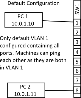
The above diagram shows the default set up on an eight port switch with two machines connected. The two machines can ping each other as they are both on the same VLAN and are both in the same IP network (assume a netmask of something like 255.255.255.0). So far so easy…
In the next diagram I’ve reconfigured port eight on the switch so that it is in VLAN 2. How this is done varies from switch to switch but the basic process will be to first create a VLAN with a new ID number and then add whichever ports you want to belong to that VLAN. The ports that are added to the new VLAN are called access ports and carry traffic only for VLAN 2.
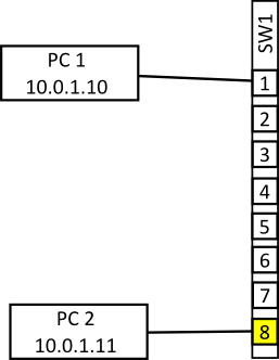
In the above diagram we again see two machines connected to the switch but this time PC 2 is on a port configured to be in VLAN 2. When the machines try to ping one another now they is no reply. Packets injected into the switch by PC 2 can not access any other switch port since there are on other ports configured to be on VLAN 2. Effectively it’s as if PC 2 is on it’s own switch or LAN. If there was an appropriately configured PC connected to any port from 2 through 7 then PC 1 could still ping them but PC 2 is not reachable by PC 1. Note that both PC 1 and PC 2 both still have IP addresses in the same subnet but can’t communicate, this clearly shows that VLANs are a layer two construct.
I’m now going to move PC 2 into the 10.0.2.0/24 range since it’ll be easier to see what is happening with the configuration if the IP address matches the VLAN tag but I want to emphasise that this is not necessary from a technical point of view. All the various different VLANs could all use the 10.0.1.0/24 range at the same time quite happily as long as there was no need for machines on different VLANs to directly communicate. If machines on different VLANs do need to communicate a layer three router will be required to shepherd packets from one VLAN to the other. This routing could be done either by a dedicated router or the switch itself if it has layer three functionality.
Since a switch configured with a single port on a different VLAN isn’t very interesting (in fact it’s almost completely pointless, using it as a management port for the switch is about it’s only use) in the next example I’ve added a few more machines and another switch and the two switches have been linked together (with a cross over cable if necessary).
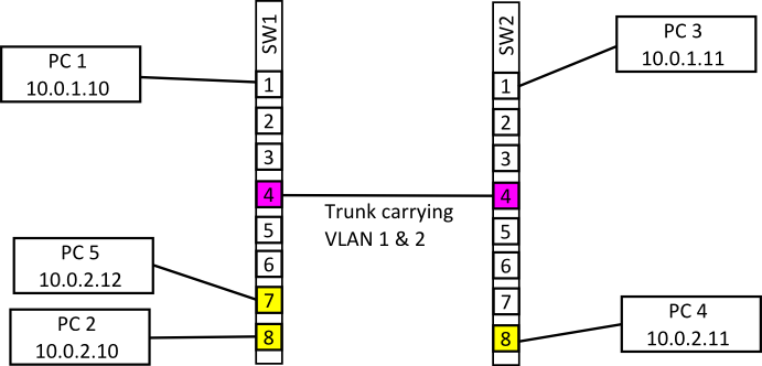
The diagram above shows the SW1 now has port 7 in VLAN 1 as well as port 8, on SW2 only port 8 is in VLAN 2. All the other ports on both switches are in the default VLAN. When the two switches are first connected PC 1 and PC 3 can communicate since the ports linking the two switches are both in the default VLAN and so packets will pass over the link. Also PC 2 and PC 5 can also communicate since they are both in VLAN 2 and they are on the same switch. PC 4 can’t communicate with any machine though since it’s isolated on SW2. What we want is for PC 2 & 5 to be able to communicate with PC 4 and for PC 1 & 3 to be able to communicate, the way this is achieved is by setting up a trunk.
As with setting up an access port for a VLAN setting up a trunk will vary from switch to switch but generally you will need to select the port that will be made into a trunk and then tell the switch which VLANs that port will be carrying. This configuration will need to be carried out on both switches and the two connected ports should carry the same VLAN range. Note that it’s usually possible to select a range of VLANs that a trunk will carry which can greatly reduce the configuration if VLANs are heavily used. Once the configuration is complete PC 4 should be able to access PC 5 & 2 and vice versa.
Under the hood what is happening is that switch is tagging the ethernet frames with a VLAN number as they are entering the trunk so that the destination switch knows which VLAN the frame is for. The tag is stripped of the frame before it is delivered to the client so from the point of view of the connected machines they are on their own private network.
the above examples use a set up called port base or static VLAN assignment because the administrator of the switch sets the VLAN number on the port before the client attaches to it. The client then assumes the VLAN number on that port. An alternative management method is dynamic VLAN assignment to the port. When a client attaches to the port a VLAN number is assigned based on, for example, the MAC address of the connecting machine. Dynamic assignment is useful in environments where clients often connect to different and unpredictable ports (e.g. hot desking with laptops). The port VLAN assignment is done by a VLAN Policy Management Server.